Display ASCII characters read from keyboard on VGA
In the previous project, we displayed the scan code of a key (jp109) on the VGA.
 Key              MakeCode  BreakCode
---------         --------- -----
[1 !] ...         16 ... 16 f0 16              // 16: Make Code; f0 16: Break Code (released)
[2 "] ...         1e ... 1e f0 1e              // ...: held down without being released (repeat)
[3 #] ...         26 ... 26 f0 26
[4 $] ...         25 ... 25 f0 25
[5 %] ...         2e ... 2e f0 2e
[6 &] ...         36 ... 36 f0 36
[7 '] ...         3d ... 3d f0 3d
[8 (] ...         3e ... 3e f0 3e
[9 )] ...         46 ... 46 f0 46
[0  ] ...         45 ... 45 f0 45

[A  ] ...         1c ... 1c f0 1c
[B  ] ...         32 ... 32 f0 32
[C  ] ...         21 ... 21 f0 21
[D  ] ...         23 ... 23 f0 23
[E  ] ...         24 ... 24 f0 24
[F  ] ...         2b ... 2b f0 2b
[G  ] ...         34 ... 34 f0 34
[H  ] ...         33 ... 33 f0 33
[I  ] ...         43 ... 43 f0 43
[J  ] ...         3b ... 3b f0 3b
[K  ] ...         42 ... 42 f0 42
[L  ] ...         4b ... 4b f0 4b
[M  ] ...         3a ... 3a f0 3a
[N  ] ...         31 ... 31 f0 31
[O  ] ...         44 ... 44 f0 44
[P  ] ...         4d ... 4d f0 4d
[Q  ] ...         15 ... 15 f0 15
[R  ] ...         2d ... 2d f0 2d
[S  ] ...         1b ... 1b f0 1b
[T  ] ...         2c ... 2c f0 2c
[U  ] ...         3c ... 3c f0 3c
[V  ] ...         2a ... 2a f0 2a
[W  ] ...         1d ... 1d f0 1d
[X  ] ...         22 ... 22 f0 22
[Y  ] ...         35 ... 35 f0 35
[Z  ] ...         1a ... 1a f0 1a

[- =] ...         4e ... 4e f0 4e
[^ ~] ...         55 ... 55 f0 55
[\ |] ...         6a ... 6a f0 6a
[@ `] ...         54 ... 54 f0 54
[[ {] ...         5b ... 5b f0 5b
[; +] ...         4c ... 4c f0 4c
[: *] ...         52 ... 52 f0 52
[] }] ...         5d ... 5d f0 5d
[, <] ...         41 ... 41 f0 41
[. >] ...         49 ... 49 f0 49
[/ ?] ...         4a ... 4a f0 4a
[\ _] ...         51 ... 51 f0 51

[Tab] ...         0d ... 0d f0 0d
[Enter] ...       5a ... 5a f0 5a
[Space] ...       29 ... 29 f0 29
[Back space] ...  66 ... 66 f0 66
[Esc] ...         76 ... 76 f0 76
[L Shift] ...     12 ... 12 f0 12
[R Shift] ...     59 ... 59 f0 59
[L Ctrl] ...      14 ... 14 f0 14
[L Alt] ...       11 ... 11 f0 11
[Scroll] ...      7e ... 7e f0 7e
[無変換] ...       67 ... 67 f0 67
[変換]   ...       64 ... 64 f0 64
[カタカナ] ...     13 ... 13 f0 13

[F1] ...          05 ... 05 f0 05
[F2] ...          06 ... 06 f0 06
[F3] ...          04 ... 04 f0 04
[F4] ...          0c ... 0c f0 0c
[F5] ...          03 ... 03 f0 03
[F6] ...          0b ... 0b f0 0b
[F7] ...          83 ... 83 f0 83
[F8] ...          0a ... 0a f0 0a
[F9] ...          01 ... 01 f0 01
[F10] ...         09 ... 09 f0 09
[F11] ...         78 ... 78 f0 78
[F12] ...         07 ... 07 f0 07

[R Ctrl] ...      e0 14 ... e0 14 e0 f0 14     // Extended Key (with e0)
[R Alt] ...       e0 11 ... e0 11 e0 f0 11
[L Arrow] ...     e0 6b ... e0 6b e0 f0 6b
[R Arrow] ...     e0 74 ... e0 74 e0 f0 74
[U Arrow] ...     e0 75 ... e0 75 e0 f0 75
[D Arrow] ...     e0 72 ... e0 72 e0 f0 72
[L Windows] ...   e0 1f ... e0 1f e0 f0 1f
[R Windows] ...   e0 27 ... e0 27 e0 f0 27
[Insert] ...      e0 70 ... e0 70 e0 f0 70
[Delete] ...      e0 71 ... e0 71 e0 f0 71
[Home] ...        e0 6c ... e0 6c e0 f0 6c
[End] ...         e0 69 ... e0 69 e0 f0 69
[PageUp] ...      e0 7d ... e0 7d e0 f0 7d
[PageDown] ...    e0 7a ... e0 7a e0 f0 7a
[Insert] ...      e0 70 ... e0 70 e0 f0 70
[Delete] ...      e0 71 ... e0 71 e0 f0 71
[App] ...         e0 2f ... e0 2f e0 f0 2f

[NumLock] ...     77 ... 77 f0 77
[/] ...           e0 4a ... e0 4a e0 f0 4a
[*] ...           7c ... 7c f0 7c
[-] ...           7b ... 7b f0 7b
[+] ...           79 ... 79 f0 79
[.] ...           71 ... 71 f0 71
[0] ...           70 ... 70 f0 70
[1] ...           69 ... 69 f0 69
[2] ...           72 ... 72 f0 72
[3] ...           7a ... 7a f0 7a
[4] ...           6b ... 6b f0 6b
[5] ...           73 ... 73 f0 73
[6] ...           74 ... 74 f0 74
[7] ...           6c ... 6c f0 6c
[8] ...           75 ... 75 f0 75
[9] ...           7d ... 7d f0 7d
[Enter] ...       e0 5a ... e0 5a e0 f0 5a

[Prt Scrn] ...    e0 12 e0 7c    e0 7c ... e0 7c    e0 f0 7c e0 f0 12
[Pause]           e1 14 77 e1 f0 14 f0 77     // no break code, no repeat
In this project (project name: riscv_display_ascii), you write a program to translate the scan code to the ASCII code and put it in the char RAM for display. For example, if you pressed a key 'L' and release it immediately, the keyboard controller will give you a scan code of three bytes: 0x4b 0xf0 0x4b. Then you convert the scan code to the ASCII code 'l' (0x6c). If you pressed a key 'Left Shift', then 'L', and release 'L' and then 'Left Shift', the keyboard controller will give you the scan codes of six bytes: 0x12 0x4b 0xf0 0x4b 0xf0 0x12. Then you convert the scan codes to the ASCII code 'L' (0x4c). That is,
0x4b 0xf0 0x4b                : 'l' (ASCII 0x6c)
0x12 0x4b 0xf0 0x4b 0xf0 0x12 : 'L' (ASCII 0x4c)
You can refer to the following flow chart to develop the program. It ignores the extended keys. You can deal with the keys one by one, or use a translation table to get the ASCII from the table by using the make code as the index of the table.

In case you use the translation table, the make code is used as the index of the table and the contents of the table are ASCII codes. The translation table can be put next to the character RAM and you can use "initial" statement to initialize the table.

You can write the assembly code (riscv_inst_ram_ascii.s) as follows, and translate it to Verilog HDL code by using rivasm.
1 2 3 4 5 6 7 8 9 10 11 12 13 14 15 16 17 18 19 20 21 22 23 24 25 26 27 28 29 30 31 32 33 34 35 36 37 38 39 40 41 42 43 44 45 46 47 48 49 50 51 52 53 54 55 |
.text # code segment main: lui s2, 0xc0000 # vram space: c0000000 - dfffffff !!!!!!!!!!!!!!!!!! s2: vram address mv t0, zero # t0: char row number (0 - 59) use 8-bit mv t1, zero # t1: char col number (0 - 79) use 8-bit li a3, 80 # 80 chars per line lui a4, 0xff0 # background color csrw 0x800, a4 # to caret register li s3, 0x4b00 # 0x12c0 << 2 # table entry add s3, s3, s2 # translation table base address !!!!!!!!!!!!!!!!!!! s3: table base address addi s4, x0, 0 # s4: last key !!!!!!!!!!!!!!!!!!!!!!!!!!!!!!!!!!!!! s4: last key addi s5, x0, 0 # s5: shift tag !!!!!!!!!!!!!!!!!!!!!!!!!!!!!!!!!!!! s5: shift tag read_kbd: csrr a0, 0x800 # read kbd: {0,ready,byte} andi a1, a0, 0x100 # check if ready beqz a1, read_kbd # if no key pressed, wait andi a1, a0, 0xff # ready, get data, a1: key !!!!!!!!!!!!!!!!!!!!!!!!! a1: key l_shift: addi a5, x0, 0x12 # left shift beq a1, a5, check_last_key r_shift: addi a5, x0, 0x59 # right shift beq a1, a5, check_last_key not_shift: # put your codes here convert_key: beq s5, x0, look_up # check shift ori a1, a1, 0x80 # with shift (makecode < 0x80) look_up: # lookup table slli a1, a1, 2 # to byte offset add s6, s3, a1 # char ram address lw s7, 0(s6) # get ascii beq s7, x0, update_last_key # ignore ascii 0 write_to_char_ram: sw s7, 0(s2) # to display addi s2, s2, 4 # next address output_caret: slli t3, t0, 8 # row << 8 or t3, t3, t1 # row,col lui a4, 0xff0 # background color or a4, a4, t3 # back,row,col csrw 0x800, a4 # to caret register j update_last_key check_last_key: addi a5, x0, 0xf0 # break f0 beq s4, a5, clear_shift_tag set_shift_tag: addi s5, x0, 1 # set shift tag j update_last_key clear_shift_tag: addi s5, x0, 0 # clear shift tag update_last_key: mv s4, a1 # last key = key j read_kbd .end |
Following is the Verilog HDL code that implements character RAM and scancode-to-ASCII translation table.
1 2 3 4 5 6 7 8 9 10 11 12 13 14 15 16 17 18 19 20 21 22 23 24 25 26 27 28 29 30 31 32 33 34 35 36 37 38 39 40 41 42 43 44 45 46 47 48 49 50 51 52 53 54 55 56 57 58 59 60 61 62 63 64 65 66 67 68 69 70 71 72 73 74 75 76 77 78 79 80 81 82 83 84 85 86 87 88 89 |
module riscv_char_ram_ascii (clk,addr,dout,din,we); // single-port ram input clk; input [3:0] we; input [12:0] addr; // word address input [6:0] din; output [6:0] dout; reg [12:0] addr_reg; reg [6:0] char_ram [0:8191]; // 80 * 60 + 256 = 4800 + 256 = 5056 always @(posedge clk) begin // posedge read and write if (we[0]) // should be byte-addressable char_ram[addr] <= din; // write char ram addr_reg <= addr; // register read address end assign dout = char_ram[addr_reg]; // read char ram initial begin char_ram[13'd2351] = 7'h48; // H char_ram[13'd2352] = 7'h65; // e char_ram[13'd2353] = 7'h6c; // l char_ram[13'd2354] = 7'h6c; // l char_ram[13'd2355] = 7'h6f; // o char_ram[13'd2356] = 7'h2c; // , char_ram[13'd2357] = 7'h20; // char_ram[13'd2358] = 7'h52; // R char_ram[13'd2359] = 7'h49; // I char_ram[13'd2360] = 7'h53; // S char_ram[13'd2361] = 7'h43; // C char_ram[13'd2362] = 7'h2d; // - char_ram[13'd2363] = 7'h56; // V char_ram[13'd2364] = 7'h20; // char_ram[13'd2365] = 7'h43; // C char_ram[13'd2366] = 7'h50; // P char_ram[13'd2367] = 7'h55; // U char_ram[13'd2368] = 7'h21; // ! // translation table: scancode to ascii without shift; base address: 0x12c0 char_ram[13'h12c0] = 7'h00; char_ram[13'h12c1] = 7'h00; char_ram[13'h12c2] = 7'h00; char_ram[13'h12c3] = 7'h00; char_ram[13'h12c4] = 7'h00; char_ram[13'h12c5] = 7'h00; char_ram[13'h12c6] = 7'h00; char_ram[13'h12c7] = 7'h00; char_ram[13'h12c8] = 7'h00; char_ram[13'h12c9] = 7'h00; char_ram[13'h12ca] = 7'h00; char_ram[13'h12cb] = 7'h00; char_ram[13'h12cc] = 7'h00; char_ram[13'h12cd] = 7'h00; char_ram[13'h12ce] = 7'h00; char_ram[13'h12cf] = 7'h00; char_ram[13'h12d0] = 7'h00; char_ram[13'h12d1] = 7'h00; char_ram[13'h12d2] = 7'h00; char_ram[13'h12d3] = 7'h00; char_ram[13'h12d4] = 7'h00; char_ram[13'h12d5] = 7'h71; // 'q' make code: 0x15; 0x12c0 + 0x15 = 0x12d5 char_ram[13'h12d6] = 7'h31; // '1' make code: 0x16; 0x12c0 + 0x16 = 0x12d6 // ... char_ram[13'h133f] = 7'h00; // translation table: scancode to ascii with shift; address: 0x12c0 + 0x80 = 0x1340; note that the makecode < 0x80 char_ram[13'h1340] = 7'h00; char_ram[13'h1341] = 7'h00; char_ram[13'h1342] = 7'h00; char_ram[13'h1343] = 7'h00; char_ram[13'h1344] = 7'h00; char_ram[13'h1345] = 7'h00; char_ram[13'h1346] = 7'h00; char_ram[13'h1347] = 7'h00; char_ram[13'h1348] = 7'h00; char_ram[13'h1349] = 7'h00; char_ram[13'h134a] = 7'h00; char_ram[13'h134b] = 7'h00; char_ram[13'h134c] = 7'h00; char_ram[13'h134d] = 7'h00; char_ram[13'h134e] = 7'h00; char_ram[13'h134f] = 7'h00; char_ram[13'h1350] = 7'h00; char_ram[13'h1351] = 7'h00; char_ram[13'h1352] = 7'h00; char_ram[13'h1353] = 7'h00; char_ram[13'h1354] = 7'h00; char_ram[13'h1355] = 7'h51; // 'Q' make code: 0x15; 0x1340 + 0x15 = 0x1355 char_ram[13'h1356] = 7'h21; // '!' make code: 0x16; 0x1340 + 0x16 = 0x1356 // ... char_ram[13'h13bf] = 7'h00; end endmodule |
Display example (input from keyboard)
Project
- Display ASCII characters read from keyboard on VGA (project name: riscv_display_ascii, referring to the previous project: riscv_rv32i_display_scan_codes, use riscv_char_ram_ascii.v and riscv_inst_ram_ascii.v; others are the same).
Pin assignments:set_location_assignment PIN_M9 -to sys_clk set_location_assignment PIN_P22 -to clrn set_location_assignment PIN_B6 -to b[0] set_location_assignment PIN_B7 -to b[1] set_location_assignment PIN_A8 -to b[2] set_location_assignment PIN_A7 -to b[3] set_location_assignment PIN_L7 -to g[0] set_location_assignment PIN_K7 -to g[1] set_location_assignment PIN_J7 -to g[2] set_location_assignment PIN_J8 -to g[3] set_location_assignment PIN_A9 -to r[0] set_location_assignment PIN_B10 -to r[1] set_location_assignment PIN_C9 -to r[2] set_location_assignment PIN_A5 -to r[3] set_location_assignment PIN_H8 -to hs set_location_assignment PIN_G8 -to vs set_location_assignment PIN_D3 -to ps2_clk set_location_assignment PIN_G2 -to ps2_data
- Develop an editor that can deal with ENTER and BackSpace keys (project name: riscv_display_editor).
- Use arrow keys to move a block (ASCII 127 in this material) on the screen.

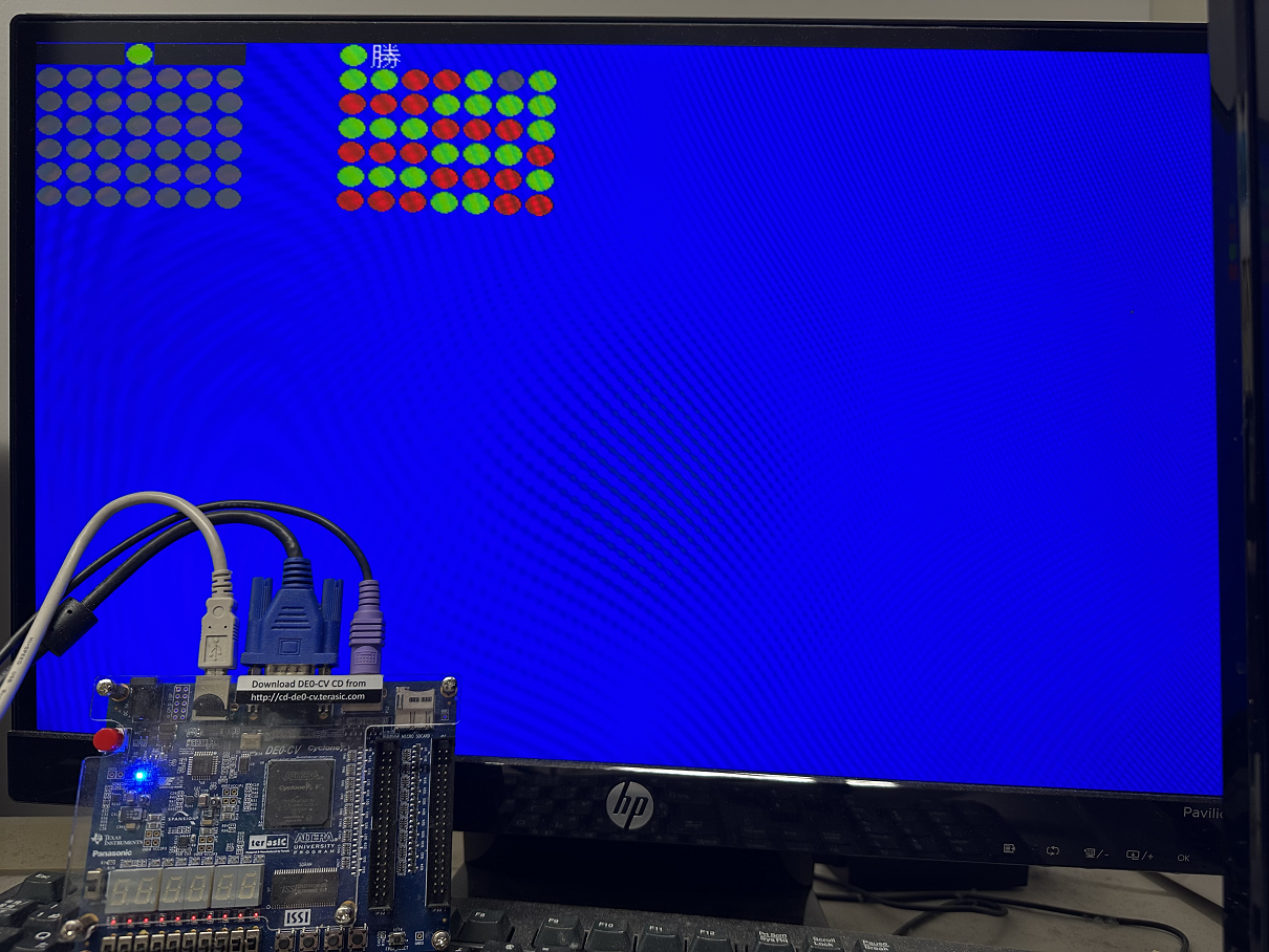
- Develop Connect4 with AI. Try connect4.sof
- Develop other games.
Exercise: Design RV32IM CPU (MUL/DIV/REM)
Design an rv32m.v and add it to riscv_rv32i_cpu.v so that you can have a riscv_rv32im_cpu.v. See RISC-V Assembly Program Simulator and RV32IM CPU Design.
mul    rd, rs1, rs2
mulh   rd, rs1, rs2
mulhsu rd, rs1, rs2
mulhu  rd, rs1, rs2
div    rd, rs1, rs2
divu   rd, rs1, rs2
rem    rd, rs1, rs2
remu   rd, rs1, rs2
Also see single_cycle_computer_simulation.pdf.
An implementation example of unsigned restoring division is shown below.
1 2 3 4 5 6 7 8 9 10 11 12 13 14 15 16 17 18 19 20 21 22 23 24 25 26 27 28 29 30 31 32 33 34 35 36 37 38 39 40 41 42 43 44 45 |
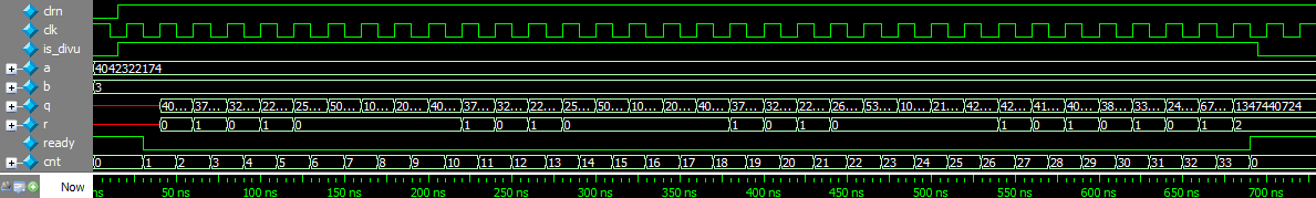
module divu ( // unsigned div input clk, input clrn, input is_divu, // decoded instruction, start cnt if is_divu == 1 for waiting result input [31:0] a, b, // a / b output [31:0] q, r, // quotient, remainder output ready // PC and regfile write enable ); reg [5:0] cnt; // 0-63 counter used for waiting always @ (negedge clk or negedge clrn) begin if (!clrn) begin cnt <= 0; end else begin if (is_divu) begin if (cnt == 6'd33) // 1: load; 2-33: 32 cycles for divu cnt <= 6'd0; else cnt <= cnt + 6'd1; end end end assign ready = ~|cnt; // ready = 1 if cnt == 0 reg [31:0] reg_a; // load a initially reg [32:0] reg_r; // reg_r[32]: sign reg [31:0] reg_b; // a / b wire [32:0] temp_r = {reg_r[31:0],reg_a[31]} - {1'b0,reg_b}; // 2r - b always @ (posedge clk) begin // 31,..., 0 bit if (cnt == 1) begin // 1,...,33 cnt reg_a <= a; // load a reg_b <= b; // load b reg_r <= 0; // remainder = 0 end else if (!ready) begin reg_a <= {reg_a[30:0],~temp_r[32]}; // 2q + q_i reg_r <= temp_r[32] ? {reg_r[31:0],reg_a[31]} : temp_r; // remainder end end assign q = reg_a; assign r = reg_r[31:0]; endmodule |
Test bench:
1 2 3 4 5 6 7 8 9 10 11 12 13 14 15 16 17 18 19 20 21 22 23 24 |
`timescale 1ns/1ns
module divu_tb;
    reg         clk;
    reg         clrn;
    reg         is_divu;
    reg  [31:0] a, b;
    wire [31:0] q, r;
    wire        ready;

    divu i0 (clk,clrn,is_divu,a,b,q,r,ready);

    initial begin
             clrn    = 0;
             is_divu = 0;
             clk     = 1;
             a       = 32'hf0f0f0fe;
             b       = 32'h00000003;
        #15  clrn    = 1;
             is_divu = 1;
        #680 is_divu = 0; // 34 cycles
        #45  $stop;
    end
    always #10 clk = !clk; // cycle time = 20ns
endmodule
|
Waveform:
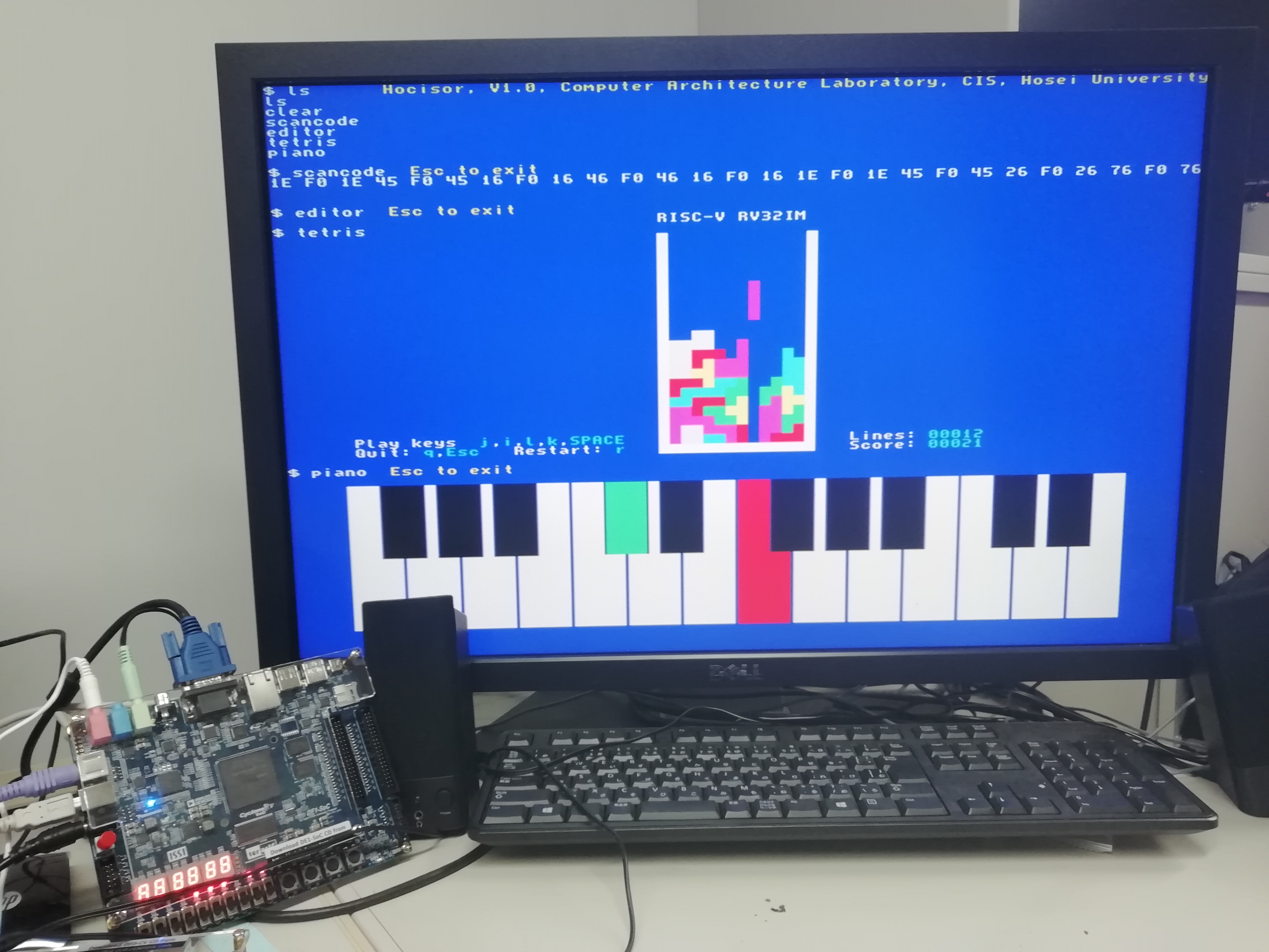
Hocisor - A computer system