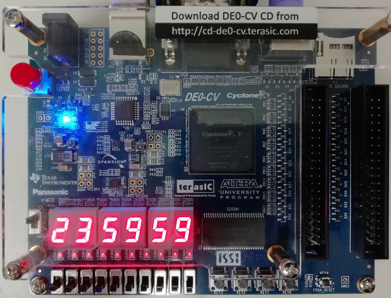
Digital Clock
Exercise
Design a digital clock to show "minute second" (from 00 00 to 59 59) with 7-segment LEDs (0: light on). Below is the top module of the project. It invokes gen_sclk module and min_sec module.
1 2 3 4 5 6 7 8 9 10 11 12 13 |
module digital_clock (sys_clk, m1, m0, s1, s0); input sys_clk; // system clock, 50MHz output [6:0] m1, m0; // seven segment LED minute 00-59 output [6:0] s1, s0; // seven segment LED second 00-59 wire sec_clk; // second clock, 1Hz // generate sec_clk (1Hz) from sys_clk (50MHz) gen_sclk sec (sys_clk, sec_clk); // digital clock (minite second): 00 00 - 59 59 min_sec ms (sec_clk, m1, m0, s1, s0); endmodule |
The following is an example code of min_sec.v. You can write your code in the places of "// ... ...".
1 2 3 4 5 6 7 8 9 10 11 12 13 14 15 16 17 18 19 20 21 22 23 24 25 26 27 28 29 30 31 32 33 34 35 36 37 38 39 40 41 |
module min_sec (sec_clk, m1, m0, s1, s0); input sec_clk; // 1Hz output [6:0] m1, m0; // seven segment LED minute 00-59 output [6:0] s1, s0; // seven segment LED second 00-59 reg [2:0] min1 = 0, sec1 = 0; // 0 - 5 reg [3:0] min0 = 0, sec0 = 0; // 0 - 9 always @ (posedge sec_clk) begin if (sec0 == 4'd9) begin sec0 <= 0; if (sec1 == 3'd5) begin sec1 <= 0; // ... ... for min0 and min1 end else begin sec1 <= sec1 + 3'd1; end end else begin sec0 <= sec0 + 4'd1; end end function [6:0] seg7; input [3:0] q; case (q) 4'd0 : seg7 = 7'b1000000; // ... ... 4'd9 : seg7 = 7'b0010000; default: seg7 = 7'b1111111; // light off endcase endfunction assign s0 = seg7(sec0); assign s1 = seg7({1'b0,sec1}); assign m0 = seg7(min0); assign m1 = seg7({1'b0,min1}); endmodule |
Write a test bench digital_clock_tb.v to simulate digital_clock.v with ModelSim. The image below shows the waveforms from 09:40 to 10:10. You can use add wave -r /* to show the waveforms of internal signals.
Note that the sys_clk is 50MHz. To generate sec_clk of 1Hz, you should divide sys_clk by 50,000,000. The waveform above shows sys_clk/10.
Implement it on FPGA. Pin assignments:
set_location_assignment PIN_U21 -to s0[0]
set_location_assignment PIN_V21 -to s0[1]
set_location_assignment PIN_W22 -to s0[2]
set_location_assignment PIN_W21 -to s0[3]
set_location_assignment PIN_Y22 -to s0[4]
set_location_assignment PIN_Y21 -to s0[5]
set_location_assignment PIN_AA22 -to s0[6]
set_location_assignment PIN_AA20 -to s1[0]
set_location_assignment PIN_AB20 -to s1[1]
set_location_assignment PIN_AA19 -to s1[2]
set_location_assignment PIN_AA18 -to s1[3]
set_location_assignment PIN_AB18 -to s1[4]
set_location_assignment PIN_AA17 -to s1[5]
set_location_assignment PIN_U22 -to s1[6]
set_location_assignment PIN_Y19 -to m0[0]
set_location_assignment PIN_AB17 -to m0[1]
set_location_assignment PIN_AA10 -to m0[2]
set_location_assignment PIN_Y14 -to m0[3]
set_location_assignment PIN_V14 -to m0[4]
set_location_assignment PIN_AB22 -to m0[5]
set_location_assignment PIN_AB21 -to m0[6]
set_location_assignment PIN_Y16 -to m1[0]
set_location_assignment PIN_W16 -to m1[1]
set_location_assignment PIN_Y17 -to m1[2]
set_location_assignment PIN_V16 -to m1[3]
set_location_assignment PIN_U17 -to m1[4]
set_location_assignment PIN_V18 -to m1[5]
set_location_assignment PIN_V19 -to m1[6]
set_location_assignment PIN_U20 -to h0[0]
set_location_assignment PIN_Y20 -to h0[1]
set_location_assignment PIN_V20 -to h0[2]
set_location_assignment PIN_U16 -to h0[3]
set_location_assignment PIN_U15 -to h0[4]
set_location_assignment PIN_Y15 -to h0[5]
set_location_assignment PIN_P9 -to h0[6]
set_location_assignment PIN_N9 -to h1[0]
set_location_assignment PIN_M8 -to h1[1]
set_location_assignment PIN_T14 -to h1[2]
set_location_assignment PIN_P14 -to h1[3]
set_location_assignment PIN_C1 -to h1[4]
set_location_assignment PIN_C2 -to h1[5]
set_location_assignment PIN_W19 -to h1[6]
set_location_assignment PIN_V15 -to sys_clk
Option
Design a digital clock showing hh:mm:ss and implement it on FPGA. You can use switches to adjust the clock frequencies.

